

Products
DRG-1801 Frequency isolated safety barrier

Classification:
DRG series
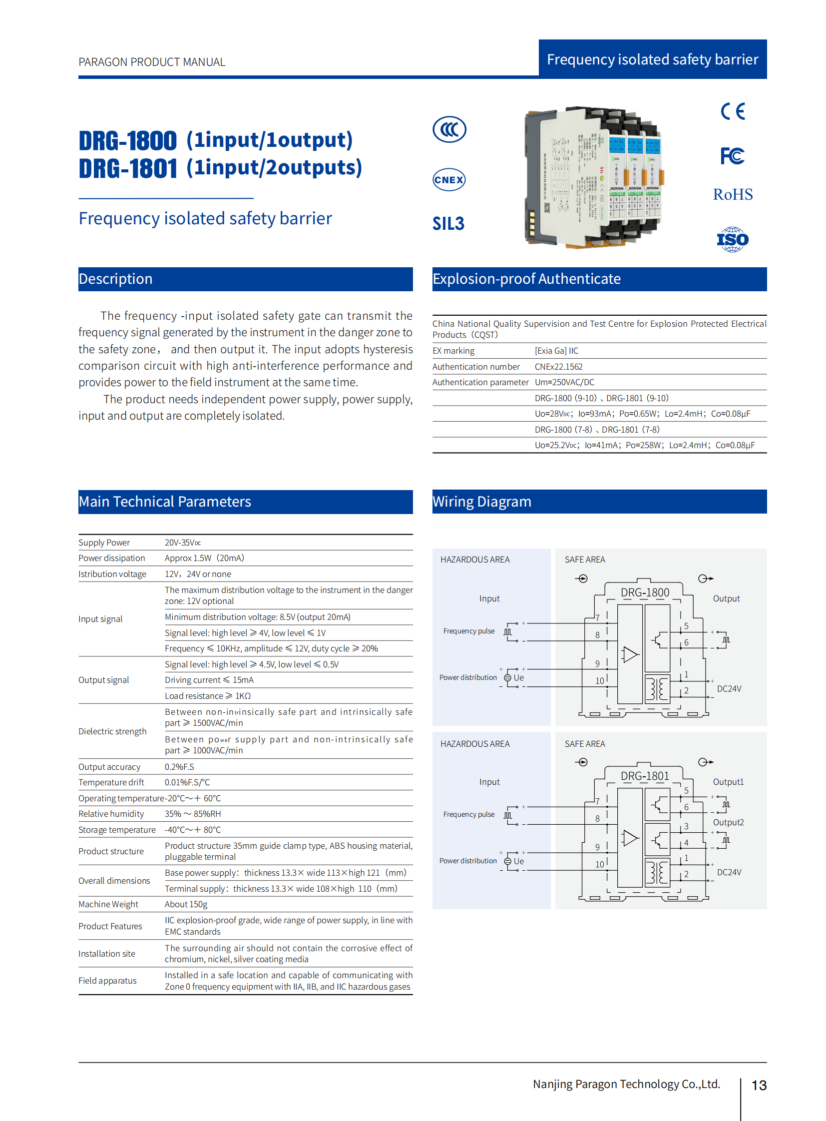
The frequency -input isolated safety gate can transmit the frequency signal generated by the instrument in the danger zone to the safety zone, and then output it. The input adopts hysteresis comparison circuit with high anti-interference performance and provides power to the field instrument at the same time. The product needs independent power supply, power supply, input and output are completely isolated.
Number of channels:
1input/2outputs
Input:
frequency(0.1~100kHz)
Power distribution:
Output:
Power supply mode:
Power connection mode:

- 产品对比
Contrast
| General | |
| Number of channels | 1input/2output |
| Insulation strength | 1500VAC/min between intrinsically safe/non intrinsically safe terminals, 1000VAC/min between non intrinsically safe terminals |
| Output accuracy | 0.2% F.S. |
| Temperature drift | 0.01%F.S/C |
| Insulation resistance | Non intrinsic safety end - intrinsic safety end≥100MΩ, power supply - non intrinsic safety end≥100MΩ |
| Electromagnetic compatibility | Compliant with IEC 61326-1 (GB/T 18268), IEC 61326-3-1 |
| EX marking | [Ex ia Ga]ⅡC |
| Distribution voltage | 12V,24Vor none |
| Weight | About 150g |
| Connected field equipment | Installed in a safe location and capable of communicating with Zone 0 frequency equipment with IIA, IIB, and IIC hazardous gases |
| Applicable locations | Zone 0, Zone 1, Zone 2, IIA, IIB, IIC hazardous areas |
| Input data | |
| Maximum distribution voltage for hazardous area instruments | Switch |
| Minimum distribution voltage | 8.5V (output 20mA) |
| Signal Level | High Level≥4V;Low Level≤1V |
| Frequency | Frequency ≤ 10KHz, amplitude ≤ 12V, duty cycle ≥ 20% |
| Output data | |
| Signal Level | High Level≥4.5V;Low Level≤0.5V |
| Drive current | ≤15mA |
| Load resistance | ≥1KΩ |
| Power supply | |
| Supply voltage(Ue) | 20~35V DC |
| Power protection | Reverse protection of power supply |
| Power consumption | About 1.5W (output 20mA) |
| Power supply mode | Independent power supply |
| Power connecting mode | Terminal power supply;Base power supply |
| Overall dimension | |
| Centralized power supply | |
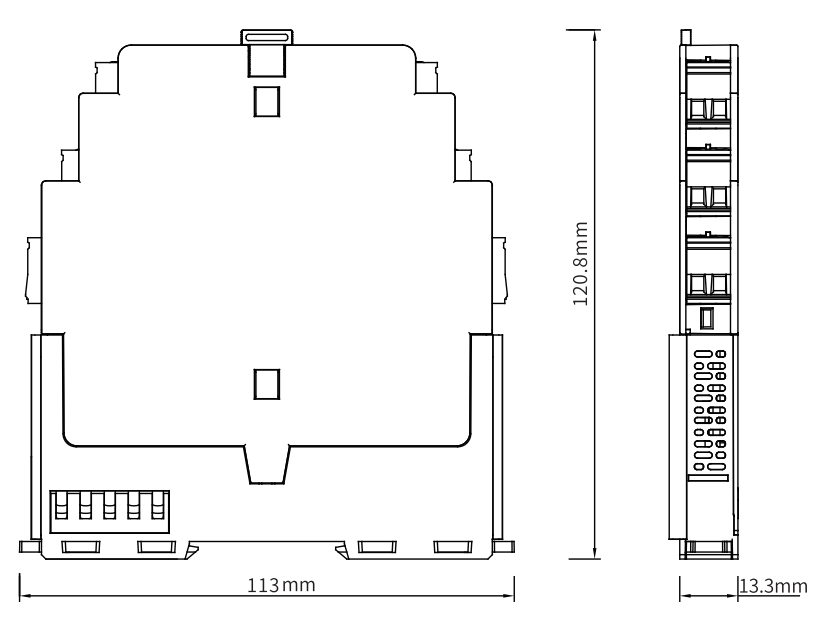
| Depth | 120.8mm |
| Height | 113mm |
| Width | 13.3mm |
| Independent power supply | |
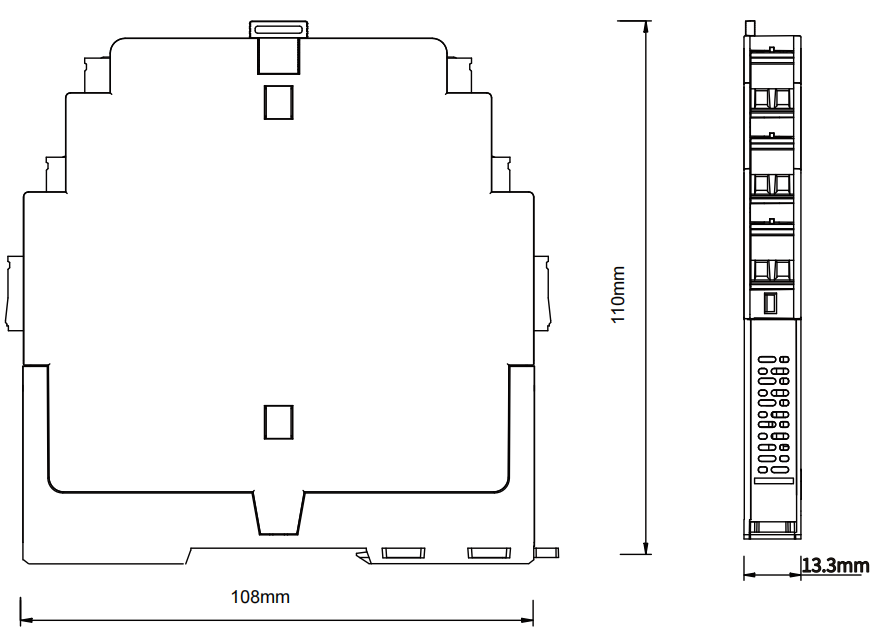
| Depth | 110mm |
| Height | 108mm |
| Width | 13.3mm |
| Housing | |
| Material | PC+ABSflame retardant |
| Degree of protection | IP20 |
| Flammability rating | UL94/V0 |
| Colour | White+Grey |
| EMC data | |
| Electrical fast transient/burst immunity | Compliant with:IEC 61326-1;A-leve |
| Surge immunity | Compliant with:IEC 61326-1;B-leve |
| Radiated,radio-frequency,electromagnetic field immunity | Compliant with:IEC 61326-1;conform to basic requirements |
| Electrostatic discharge immunity | Compliant with:IEC 61326-1;A-leve |
| Immunity to conducted disturbances, induced by radio-frequency fields | Compliant with:IEC 61326-1;conform to basic requirements |
| Low frequency common mode conduction | Compliant with:IEC 61326-1;conform to basic requirements |
| Operating conditions | |
| Continuous operating temperature | ﹣20℃~﹢60℃ |
| Storage temperature | ﹣40℃~+80℃ |
| Relative humidity | 35%~85%RH |
| Environmental requirements | There should be no strong vibrations, impacts, high currents, sparks or other electromagnetic induction effects in the surrounding environment. The air should not contain media that corrode chromium, nickel, and silver coatings, and should not contain flammable or explosive substances |
| Connection data | |
| Conductor cross section solid range | 0.5~2.5mm² |
| Conductor cross section AWG min. | 24 |
| Conductor cross section AWG max. | 12 |
| Screw thread | M3 |
| Stripping length | 8mm |
| Connection method | Screw connection |
| Tightening torque min. | 0.5 Nm |
| Tightening torque max. | 0.6 Nm |
| Installation | |
| Installation method | DIN35mm |
| 外形尺寸 | |||
| 底座集中供电型 | 端子供电型 | ||
 |
 |
||
| 安装方式 | |||
 |
 |
 |
 |
| General | |
| Number of channels | 1input/2output |
| Insulation strength | 1500VAC/min between intrinsically safe/non intrinsically safe terminals, 1000VAC/min between non intrinsically safe terminals |
| Output accuracy | 0.2% F.S. |
| Temperature drift | 0.01%F.S/C |
| Insulation resistance | Non intrinsic safety end - intrinsic safety end≥100MΩ, power supply - non intrinsic safety end≥100MΩ |
| Electromagnetic compatibility | Compliant with IEC 61326-1 (GB/T 18268), IEC 61326-3-1 |
| EX marking | [Ex ia Ga]ⅡC |
| Distribution voltage | 12V,24Vor none |
| Weight | About 150g |
| Connected field equipment | Installed in a safe location and capable of communicating with Zone 0 frequency equipment with IIA, IIB, and IIC hazardous gases |
| Applicable locations | Zone 0, Zone 1, Zone 2, IIA, IIB, IIC hazardous areas |
| Input data | |
| Maximum distribution voltage for hazardous area instruments | Switch |
| Minimum distribution voltage | 8.5V (output 20mA) |
| Signal Level | High Level≥4V;Low Level≤1V |
| Frequency | Frequency ≤ 10KHz, amplitude ≤ 12V, duty cycle ≥ 20% |
| Output data | |
| Signal Level | High Level≥4.5V;Low Level≤0.5V |
| Drive current | ≤15mA |
| Load resistance | ≥1KΩ |
| Power supply | |
| Supply voltage(Ue) | 20~35V DC |
| Power protection | Reverse protection of power supply |
| Power consumption | About 1.5W (output 20mA) |
| Power supply mode | Independent power supply |
| Power connecting mode | Terminal power supply;Base power supply |
| Overall dimension | |
| Centralized power supply | |
| Depth | 120.8mm |
| Height | 113mm |
| Width | 13.3mm |
| Independent power supply | |
| Depth | 110mm |
| Height | 108mm |
| Width | 13.3mm |
| Housing | |
| Material | PC+ABSflame retardant |
| Degree of protection | IP20 |
| Flammability rating | UL94/V0 |
| Colour | White+Grey |
| EMC data | |
| Electrical fast transient/burst immunity | Compliant with:IEC 61326-1;A-leve |
| Surge immunity | Compliant with:IEC 61326-1;B-leve |
| Radiated,radio-frequency,electromagnetic field immunity | Compliant with:IEC 61326-1;conform to basic requirements |
| Electrostatic discharge immunity | Compliant with:IEC 61326-1;A-leve |
| Immunity to conducted disturbances, induced by radio-frequency fields | Compliant with:IEC 61326-1;conform to basic requirements |
| Low frequency common mode conduction | Compliant with:IEC 61326-1;conform to basic requirements |
| Operating conditions | |
| Continuous operating temperature | ﹣20℃~﹢60℃ |
| Storage temperature | ﹣40℃~+80℃ |
| Relative humidity | 35%~85%RH |
| Environmental requirements | There should be no strong vibrations, impacts, high currents, sparks or other electromagnetic induction effects in the surrounding environment. The air should not contain media that corrode chromium, nickel, and silver coatings, and should not contain flammable or explosive substances |
| Connection data | |
| Conductor cross section solid range | 0.5~2.5mm² |
| Conductor cross section AWG min. | 24 |
| Conductor cross section AWG max. | 12 |
| Screw thread | M3 |
| Stripping length | 8mm |
| Connection method | Screw connection |
| Tightening torque min. | 0.5 Nm |
| Tightening torque max. | 0.6 Nm |
| Installation | |
| Installation method | DIN35mm |
| 外形尺寸 | |||
| 底座集中供电型 | 端子供电型 | ||
|
|
||
| 安装方式 | |||
|
|
|
|
File Name
File Size
Classification
Upload time
Download
127.6KB
Barrier
2023-09-14
207.1KB
Signal isolator
2023-09-19
158.6KB
Signal isolator
2023-09-19
File Name
Classification
Download
Address: Floor 12~13, Building 2, No.28 Dongcun Road, Jiangning District, Nanjing
Telephone:86-25-87187408/87187418
WeChat Consulting
©2023 Nanjing Paragon Technology Co., Ltd. Technical Support:China Enterprise Power Nanjing SEO Tags
©2023 NANJING PARAGON TECHNOLOGY CO., LTD
Technical Support:China Enterprise Power Nanjing SEO Tags


